
Hopefully you’ve read my previous post “How to choose the Best RV Inverter” which means you did your research, estimated your power requirements, and finally came to a decision.
You ordered your inverter and today, it arrived! You’re now ready begin your DoItYourselfRV inverter install.
If you went with a small inverter (around 75 watts), then it can be plugged into a cigarette lighter outlet.
Anything larger will need to be wired directly to your batteries.
In order to reduce the voltage loss, you need to install the inverter as close to your batteries as possible.
The inverter manual will probably suggest a wire size. Use the recommended size or larger. Remember that the bigger the wire the smaller the gauge number.
Whatever you do, you want to limit the voltage drop as much as possible.
You should make every effort to keep the loss below 0.075 volt. The table below gives the voltage drop per foot of wire for various sized inverters. This is important to consider for your RV inverter install. For other inverter sizes, the drop will be proportional.
How Long Wires Can Drop Your Inverter’s Voltage
As an example, using the table below assume that you will be installing a 2000 watt inverter (Scroll top to bottom and find 2000 watts).
It will be connected to the batteries with 5 feet of #4 AWG cable (scroll right to left from the 2000 watt load till you find the 4 column).
The voltage loss will be .0420 x 5 (length of wire between battery and RV inverter) = .210 volts.
This means that if your batteries are charged up to 13 volts, the inverter will only be seeing 12.79 volts (13 Volts – .210 of loss). It might seem to work, but you won’t like the results.
It would be much better to go to a #00 AWG cable, which will have a total of .066 volt loss, well under the recommended .075 volt loss threshold.
The best approach is simply to use the largest size that will fit in the inverter’s terminals.
RV Inverter Install: Voltage Loss Per Foot of Wire
| Wire gauge (AWG) | #0000 | #000 | #00 | #0 | #2 | #4 | #6 | #8 |
|---|---|---|---|---|---|---|---|---|
| For 100 Watt Load | 0.0004 | 0.0005 | 0.0007 | 0.0008 | 0.0013 | 0.0021 | 0.0033 | 0.0052 |
| For 500 Watt Load | 0.0021 | 0.0056 | 0.0033 | 0.0041 | 0.0065 | 0.011 | 0.0165 | 0.026 |
| For 1000 Watt Load | 0.0041 | 0.0051 | 0.0065 | 0.0081 | 0.013 | 0.021 | 0.033 | 0.052 |
| For 1500 Watt Load | 0.0062 | 0.0083 | 0.0098 | 0.0122 | 0.0195 | 0.0315 | 0.0495 | 0.078 |
| For 2000 Watt Load | 0.0082 | 0.0102 | 0.0132 | 0.0162 | 0.026 | 0.042 | 0.066 | 0.104 |
| For 3000 Watt Load | 0.0123 | 0.0153 | 0.0195 | 0.0243 | 0.039 | 0.063 | 0.066 | 0.156 |
[asa]B000GASX9O[/asa]
If you have trouble finding suitable wire for your RV inverter install, automotive battery cable or jumper cables are readily available in 4, 6, and 8 AWG (American Wire Gauge).
Welding cable comes in larger sizes, but is expensive as many times you have to buy a whole spool. If there is a supplier near you, see if they will sell the short lengths that you need instead. You might get lucky at your local welding shop.
Wiring the Inverter
The AC (Connecting the inverter to the RV electrical system) side of the RV inverter install can get more complicated. But in any case, you need to ensure that you don’t have either shore power or generator power connected to the output of the inverter.
There are several possible ways to wire your inverter. Whichever option you select, you can do the wiring with standard 14 AWG, household type nonmetallic cable.
However you do it, you absolutely must ensure that you do not have your converter turned on when the inverter is on. The problem with having both on at once, is that you are pulling current out of your batteries with the inverter, while pushing current back into them with the converter.
Since neither the inverter nor the converter are 100% efficient, each trip that current makes around the loop will waste some power as heat. You will very quickly run down the batteries until the inverter shuts off for low voltage. That will happen even if no load is connected to the inverter.
RV Inverter Installation Method 1.
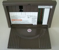
The most elegant (and of course, most expensive) solution is to connect the RV inverter directly to RV’s AC distribution boxthrough a transfer switch (keep in mind the type of switch used varies based on the power of the RV inverter and if you have a generator). The switch will automatically select shore power if it is available, and inverter power if it is not. If you go this route, you still have to avoid powering the converter from the inverter. The most common method for achieving this is to use a split distribution panel, with the converter on the part of the panel that is not connected to the inverter. If that seems like a more complex RV inverter install than you want to try, read on for how to use a relay.
RV Inverter Installation Method 2.
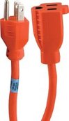
At the other extreme, you can run an extension cord from the inverter to whatever device you want to power at the moment. My first inverter installation worked that way. It gets the job done, but we very soon got tired of plugging and unplugging different devices into the extension. Though a simple RV inverter install, it left me tripping over the cord on a regular basis.
RV Inverter Installation Method 3.
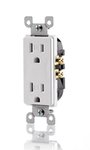
Slightly less crude, is to connect one or more dedicated outlets to the inverter. You can either install new outlets or disconnect existing outlets from the distribution box. The difficulty in accomplishing this type of installation will depend on where the outlets are located, and how hard it is to get wire to them. This RV inverter install method means having some outlets that don’t function when you are on shore power which could lead to some frustration.
RV Inverter Installation Method 4.
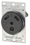
A good compromise is to install a 30 amp receptacleon the outside of your RV and then connect it to the output of the RV inverter. When you want inverter power, you just unplug the RV from shore power and plug it into the new 30 amp receptacle. With one modification, this is how my current RV is set up.
You recall that the converter and inverter should never both be on at the same time? No problem. I just flipped the circuit breaker for the converter before turning on the inverter. That is, until the time I forgot to flip it, and went to bed. I got up in a hurry when the low battery alarm on the smoke detector started beeping at me.
The reality is it should have been idiot proof. The solution is to get a relay (an electrically operated switch) with a 120 VAC coil and normally closed (n.c.) contacts that are rated at least 10 amp, DC. The figure below shows how to wire it. Connect the relay coil to the inverter output. Then disconnect the hot supply line from the converter and reconnect it through the n.c. relay contacts. Now, when the inverter is turned on or off, the relay automatically switches the converter off or on.
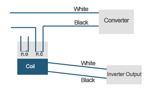
It will be most convenient to mount the relay on or close to the converter. Because the relay coil draws only a very small amount of current, you can use 18 AWG (lamp cord), or cut up a heavy duty outdoor extension cord if it needs physical protection. If your relay has any additional contacts, just ignore them.
RV Inverter Install – The Remote Switch
If you bought a remote switch for your inverter, you will need to connect it. They are usually connected with a standard telephone cable. If you need a cable longer than the one that came with the switch, it may have too much resistance to work. If your longer cable doesn’t work, you will have to substitute a cable with heavier gauge wire. Buy some 4 conductor, 18 AWG cable. Cut about 1 foot off of each end of the supplied phone cable and splice in your new wire.
For reference you can see a video regarding a RV inverter install in a Keystone Cougar 276RLSWE Fifth wheel RV Trailer.
Now with any luck, you should have your RV inverter install completed:
1. You have made sure that you won’t be destroying it by feeding shore power into it.
2. You are sure that your converter will never be powered from your inverter.
3. Congratulations. Turn it on, hit the road, and go get off the grid!

GARY, this might be a dumb question, but how to do I take the output from the inverter into the 30 amp outlet, when the output of the inverter is 4 separate 110 volt plug outlets? thank you for your help and these great ideas. Don
I have question I don’t know if someone posted before or not but let this idea share with everybody.
I have TT with 30Amps and deep cycle battery with 200Amp.
I have install the inverter close to the battery as mansion to get full power instead of drawing due to distance it’s a (Cobra CPI1575 3000w Car Power Inverter w/Remote Control) to run my hole rig without A/C & Microwave, I installed just to run all the rig receptacle for charging the phones and TV rather than running the generator day and night.
1- I don’t know where to connect the wire in the RV panel coming from the inverter close to battery?
2-so what I have did is I plug the core which connect to generator to inverter when I want to use the power for RV from battery and when I want to generator I take it back and plug it to generator.
my concert is as knew that when the generator run the converter on RV panel will charge the battery and if I have connect the same core to inverter outside will start to charge the battery and I’m taking my power from the battery we are in a circle I’m afraid that I will blow something up.
Hope my question is understood.
William,
I have been trying to figure out how to make option 4 work, so far no luck. I have even contacted the manufacture of the transfer switch, they could not help me either. It sounds easy, but in reality it is difficult. Once you have your system all hooked up, would you be so kind as to take some pictures and draw a diagram on how and where you’ve installed your transfer switch.
Thanks,
Peter
For method 4, where does the relay go in relation to the 30amp receptacle? Is it a set of wires going from the inverter to the receptacle and another set going from the inverter to the switch?
OK maybe I’ll get an answer here.
My situation:
I have a WFCO ULTRA III Power Center 30 amp converter with 3 stage charger. The power center has 120v AC and 12v DC built into it. So it gets power from shore power>converter power center>power is distributed to 12vDC and 120vAC throughout trailer. Everything in one place.
What I have consuming power:
My enclosed utility trailer has very low power needs 120vAC. There’s no air conditioner, microwave or anything else I can think of that consumes large amounts of power like that. There’s an exterior LED flood light that’s 15 watts. I’ve got a few outlets and those will probably be used to run a TV setup for the kids, charge some phones, maybe a blender or some other small cooking apparatus, a portable ice maker and that’s it. Even on my 12vDC side the power consumption is low. I’ve rigged a portable tankless water heater that feeds the trailer hot water, and a Camco catalytic heater and both use no power. The 12vDC system has the water pump, 5 LED dome lights, 2 exterior LED flood lights for the ramp area, a radio and the bathroom fan.
What I want to do:
I want to connect an inverter from the batteries to give power to the trailers outlets. I’ve settled on a 1000 watt inverter for my power needs. But as described above, it will end up creating that cycle of inverter charging the batteries via converter which is no good. Since the converter control center powers the 12vDC side, and all 120vAC outlets are coming out of the converter power center, I have to power the converter power center. I can’t simply switch off the breaker since that will kill the 12vDC power. And isolating one or two outlets for JUST the inverter isn’t what I want to do either. Basically, I want the inverter to power the converter control center, but NOT for it to charge the batteries. Any ideas on how to do this? The only thing I could find, and I think I’m on the right path with, is getting the Go Power! GPTS-30 amp automatic transfer switch.
I want to make this application idiot proof. So, plug in shore power (small generator to charge up batteries while boon docking, or powering up at home to charge batteries before our trip) I’ve got power. When out camping, flip the inverter switch and my outlets have power. The 12vDC side continues working as normal. I basically don’t want anything to blow up if for some reason someone who doesn’t know goes to flip the inverter on while the generator is running, or connected to show power. Or if the inverter is left on by accident the only thing that happens is the inverter slowly discharges the batteries. So flipping the inverter on gives power to outlets or, turning on generator powers outlets AND charges batteries back up. I’ll also be installing a 100 watt solar panel, and will expanding to around 400 watts in the future to lesson the need of running the generator as often. Any help is greatly appreciated, thanks!
I just did this for my travel trailer. I located the hot line feed to the converter and installed a separate circuit breaker for it. Now when I pull my shore line up to the front of the trailer to connect to the inverter through a conversion plug, I FIRST turn the breaker off, so no power goes to the converter, but the AC portion of the unit stays on.
It is my understanding that you can leave the stock converter connected and just the battery charger portion of the converter / charger has to be moved over to the transfer switch.
OK, the diagram didn’t work. spaces are apparently removed. Sorry.
I’ll try a diagram. ——–120V to Converter [converter]—>12V
|
Shore Power 0—————-+——–NO
3
coil –> 3 /—————AC outlets inside RV
GND /
Inverter 0——————————–NC
As you can see, without shore power, the NC leg connects inverter to AC outlets in RV.
The converter is ONLY powered by shore power, never gets inverter power.
When shore power connected, relay flips and AC outlets (and converter) are powered by shore.
Note: With a little electronics expertise, you can use a 5V or 12V relay (rather than 120VAC) and build a small electronic circuit to delay turn on/off of the relay to prevent chattering when plugged in/out.
You can have a 120V relay that has NO for shore power, NC for inverter power to the RV. Have shore power drive the relay. When shore power is present, the relay flips and shore power is driven into the RV. When shore power is missing, the inverter drives the AC outlets in the RV. No need for an outside outlet, manually plugging/unplugging.
Wire the shore side of that 120V relay (The NO input) to the converter. (not the RV side of the relay)
When attached to shore power, the AC will be powered by shore, the converter will be on.
When not attached to shore power, the AC will be powered by the inverter and DC by the battery.
I’d offer a diagram, but no way to do that here.
Thanks for sharing your plans Scott. Sounds like a great rig you’ve got there and you know a lot about RV inverters!
Just took delivery of a new 35 Georgetown. While the residential frig has its own Xantrex ProWatt 1000, it is totally dedicated to the frig. I am going to install a second ProWatt1000 (for redundancy) and they sell a nice automatic transfer switch for $60 or so. Plan to connect it to the 15 amp breaker that feeds all the non-GFI outlets (and the TVs.) I will put it right next to the Progressive Dynamics 70 amp converter and will just feed it off ht back of the 9270, which supports feed through connections. If the 9270 can pump 70 amps to the batteries, the wiring should handle the 1000 watt DC load reasonably well. They will never work at the same time since there is a transfer switch and the converter has its own breaker.
I have xantrex 458 I had installed in are class a motorhome .Which had a heartinterface in it.IT HAS NEVER WORKED. NO POWER IN THE INVERTOR MODE. iT CHARGES THE BATTERYS BUT NO TV OR FRIDGE.Is there any test I can do myself? Im tired of paying with no ansers. J Hanig
Thank you for the great article. I’d like to wire my inverter with your option # 4 but an RV tech said that I still need the converter running to power DC items in the trailer such as most lights, furnace fan, water pump, etc. So what I believe I need is to stop the converter from trying to charge the batteries when the inverter is on. Not sure if this one item can be disabled while leaving the rest of the converter functioning? Please correct me if my thinking is wrong but several people have said I’ll still need the converter to ‘distribute’ DC power for 12VDC items while using an inverter.
I’m looking at method number one for simplicity and to keep everything factory. Would I be able to disconnect the converter completely doing this method? I don’t plan on using the converter at all after I get my solar system set up, relying only on the battery bank. Any input is greatly appreciated. Thank you
You won’t need the converter if you aren’t plugged into shore power…you will be running off your battery bank. Your inverter will be running your microwave or whatnot, just leave the breaker for your converter off while the inverter is on. When you ARE on shore power, leave the inverter off and the converter on.
I like the simplicity of wiring the inverter to a 30 amp receptacle in Method 4. I am in the process of putting together a solar system on my 5th wheel for full-time rving. I am not sure how that would work with an inverter with AC input that provides a “pass through” when it detects shore power (Magnum MS2012). How does the inverter distinguish shore from inverted AC? If it can then will the 30 amp receptacle be hot when you are connected to shore?
Great tutorial. Much appreciated. One question though: wouldn’t it make more sense to put the relay to turn off the converter on the AC hot coming into the converter? This way, when you shut down the converter, everything 12v is still powered from the batteries directly. Otherwise, you are still sending AC to the converter, albeit no load is taken from the converter. There may still be a bit of phantom power being lost there.
That is why I was thinking that a 120v AC to 120v AC relay might be better. Unless cost is a factor, off course.
Thanks again,
Duh. I REALLY overlooked the whole point. Flip the switch to coach batts and walla! it works from the actual 12v cables tied directly into the main cabin power board and really does supply 12V from the ACTUAL 12V coach batteries. Sheesh – i should go to bed. Can’t wait for the inverter to arrive!
great write up! thanks! I’ve renovated a 2006 Class C after rescuing it from waterlogging unused for 4 yrs in Florida. Now it’s rebuilt and dried out in AZ and lots of upgrades inside and out nearly completed for a 5 week USA trek with our 4yo triplets.
I recently installed 4xBT105 batteries for a significant bank in a custom rail slide frame. Fun! But this is just a start and i want to wire in an inverter to not have to run the generator as much. Likely a 1500-2000w inverter is on the way!
I have one basic question (and maybe its just so simple i’m overlooking) as i diagram my wiring and calculate all of this to wire it all up….if i have to shut the converter off so as to not have a melt down…- how does it work to power the 12V items in the coach (light fixtures mainly, cig lighter outlets, marine stereos in back and ent center outside)??
I get i will have all my receptacles powered by my batt bank (or when shore or gen if plugged in that way) – but how about coach 12v lighting of i’ve no converter to step down voltage to run those loads?
There is no standard color code for converters or any other 12v wiring, so you cannot assume your converter has the same wiring colors, or even the same number of wires as the one in the article you read. Check back and see what make and model converter was referenced in the article. If yours is different (it sounds like it is), you will have to figure it out from scratch or find a schematic for your converter.
A converter has 120v input wiring, so that is likely the black and white (there IS a standard color code for 120v wiring). The converter converts the 120vac to 12dc and sends it to he battery(s) and also into the RV’s 12v wiring. There are a couple ways to do that, so I’m not going to guess the purpose of your red and blue wires. If you would identify the make and model of your converter, perhaps someone with the same model could help you out.
(1) The battery bank for the inverter can be wired directly to the inverters positive and negative terminals. There is no reason to tie those batteries to chassis ground, since the only thing they power is the inverter.
(2) You should follow the inverter manufacturer’s installation instructions for a ground, but every make of inverter I have seen has had a ground wire that goes to the chassis. This is entirely separate from the battery negative “ground”.
(3) Batteries other than the valve-regulated type (e.g. an AGM battery) give off corrosive gases and sometimes even a fine mist of the acid electrolyte (that happen during aggressive charging). The gases and mist are likely to cause damage to sensitive electronic circuit boards, so it is best to keep anything electronic away from unsealed lead-acid batteries. 10 feet seems a bit extreme, but I would want at least 3-4 feet distance. And if in a different compartment, I don’t think the actual distance is important.
It is probably a better idea to figure out how much wattage you intend to draw based on the gear you need to run off the inverter. We have an article available here: http://www.doityourselfrv.com/rv-inverter-how-to-best-option/ that goes through that selection process. 600 may not be enough to run everything you are anticipating. Hope that makes sense!
What size of inverter would you recommend for a battery bank of 2 6-volt golf cart batteries? I’m trying to decide bet a 600 and 1000 watt inverters. Thanks.
Hi! Thank you for all the info! I plan on leaving my current (newer) 6v batteries on trailer tongue hooked up to RV the way it came from dealer.. I have 3 other enersys telecom batteries which will power an inverter and then be hooked up to RV cord with a 30amp receptacle when i choose to, (these will be getting charged with solar, and sometimes a battery charger when i have shore power) My questions refer mostly to the wiring:
1.Since both battery banks are completely seperate from each other, ( other than the fact the factory ones will be getting charged by the enersys ones through inverter/RV converter) … Should i be grounding the enersys battery bank to the frame of RV? even though the other ones are also grounded to frame?
2.Should i be grounding the inverter to the frame of RV?
3. Using a gopower 3000 pure sine inverter, manual states not to have in same compartment as batteries and be at least 10 feet away…. is this truly a concern? would be so much more convenient to have everything together and close…
Any help would be greatly appreciated, hoping to do install tomorrow.
Thank you in advance!!
Hello. I had seen in another article how to completely remove your converter (with a solar setup). In the article, it says to cut the white and black wires to the converter and then cut the blue red and white.. Once removed, it says to connect the red and blue together.
Here’s my problem.. There was no red wire running to the converter. Because I’m new to electrical work, I’m puzzled. Is the red simply the positive from the battery? Can I take the blue which is still connected to the main board and run it over to the red (battery) on the board? I realize I’m a little off base asking this question because it doesn’t exactly pertain to your article but if you could help at all, that would be great! Thanks for your time.
Everything in your RV will be getting power as it would at a campsite hookup. This can be a problem because you will need a large enough battery bank and inverter to run it all! Our fridge uses 350-450 watts but it could be significantly more depending on your model. Keep that in mind when purchasing your inverter and setting up your batteries. But the basic answer to your question is yes.
Thanks. Now I’m sure I will use option 4 and plug the rv into it. Will the fridge and water pump be getting power from the inverter with this installation option? Thanks.
William,
That would apply to both options.
I have another question. Do you turn off the converter for options 3 and 4 or just for option 4? Thanks.
Thank you very much for your prompt response.
Your articles are great. Thanks to you I now have an inverter in my RV that works very well. However I want to make it idiot proof and install a Packard pr341 relay. I can’t find a wiring diagram showing which posts to hook the inverter to and which posts to hook the converter to. Would appreciate any help you could give me.
William, the short answer to your question is yes on using the inverter while the RV is running. It should not hurt to do so, we know many who have a crockpot running off an inverter with their favorite slow cook meal while traveling between destinations (my wife and I included). The inverter takes 12 volt power from the house batteries and changes it into 120 volts AC which you can use to power your microwave, your TV, etc. That reference of push or pull refers to the inverter itself being only able to do one at a time. Keep in mind I am not a trained electrical technician. But I hope my experience helps!
Gerry
I really appreciate your articles. I’ve learned a lot from them. My question is: if I turn off the converter to use the inverter, can I use the inverter while the RV is running? You mentioned that you can only either push or pull power from the house battery. And since the alternator charges the house battery when the RV is running, will it hurt to use the inverter while RV is running?
Nope, you aren’t missing anything. Some RVs are wired that way right from the factory. Winnebago has used that method in quite a few models that have small inverters dedicated to the entertainment systems only.
Good luck with your project!
First, thanks for the article and ideas.
I’m considering option #3, dedicating an outlet to the inverter ( just for the entertainment center ).
If this is the case, I should have clean power to the input side of the inverter, regardless of if the DC power is just from the battery cells themselves, or if the charger happened to be “on” due to shore power supply.
So, basically, the TV is plugged in all the time to DC inverted power: sourced from battery provided DC power or shore provided DC power.
Am I missing anything?
“As long as the batteries powering the inverter are not connected to the converter/charger in any fashion, I can see no problem. You should take precautions, though, to make sure nobody decides to hook in a battery without your knowledge. I’m sure you will say “can’t happen”, but people often forget over time, or perhaps a buddy decides to help you out with a battery while you aren’t on hand to explain why you don’t have one there. Things like that do happen, so it’s best to make sure they won’t. A simple switch on the charger power source would do the trick” – GaryRVRoamer
Thanks for the informative write up. I’m going to try option one with the transfer switch in my 1986 class C RV which has a Parallax 6300 series power center with the optional battery charger. My question is: Do I need to do anything about the converter if there is no battery attached to it? I have a separate bank of batteries that will be charging from solar panels which connect to the inverter which will supply AC power to the AC power center.
From your first page, you indicated that the danger of the converter and inverter being on at the same time is that you would be creating a loop which would discharge your battery when no load is being applied. Obviously this couldn’t happen if the converter and inverter are not attached to the same battery. However, I’m still wondering if you could see any problems arising if there is no battery connected to the converter and only the inverter is being powered? Should I just disconnect the converter as a precaution against a possible phantom load?
Cheers,
Dan
Hi Larry,
Thanks for your question. This excerpt says it best from http://www.wind-sun.com/ForumVB/showthread.php?16719-Off-Grid-Inverter-Battery-Charging
“Current either flows from the inverter to the batteries or from the batteries to the inverter. It can not do both at the same time over one set of wires. I’ve yet to see any inverter with separate wires for charging and discharging the batteries.
Even with those inverters that can do load sharing/shedding they are either drawing from the batteries or sending to them. This may change form moment to moment depending on the load draws, but it is still a one-way street. While charging no power is being drawn from the batteries. If power is being drawn from the batteries no charging is occurring.
Note that you can have a separate stand-alone charger for the batteries (as many do with inverters that have no built-in charger)”
See our post How to choose the Best RV Inverter for our favorite brands.
I like your idea of wiring a 30amp recepticale to the inverter out put. If i am using a inverter/charger will my batteries still charged? I think the answer is only when on shore power or generator.
Do you have a brand preference?