How to Check Your RV Furnace Parts
If you’ve read our previous post on RV furnace repairs and still have questions, then this article is for you. Here we will look at a more detailed explanation of the testing of individual components.
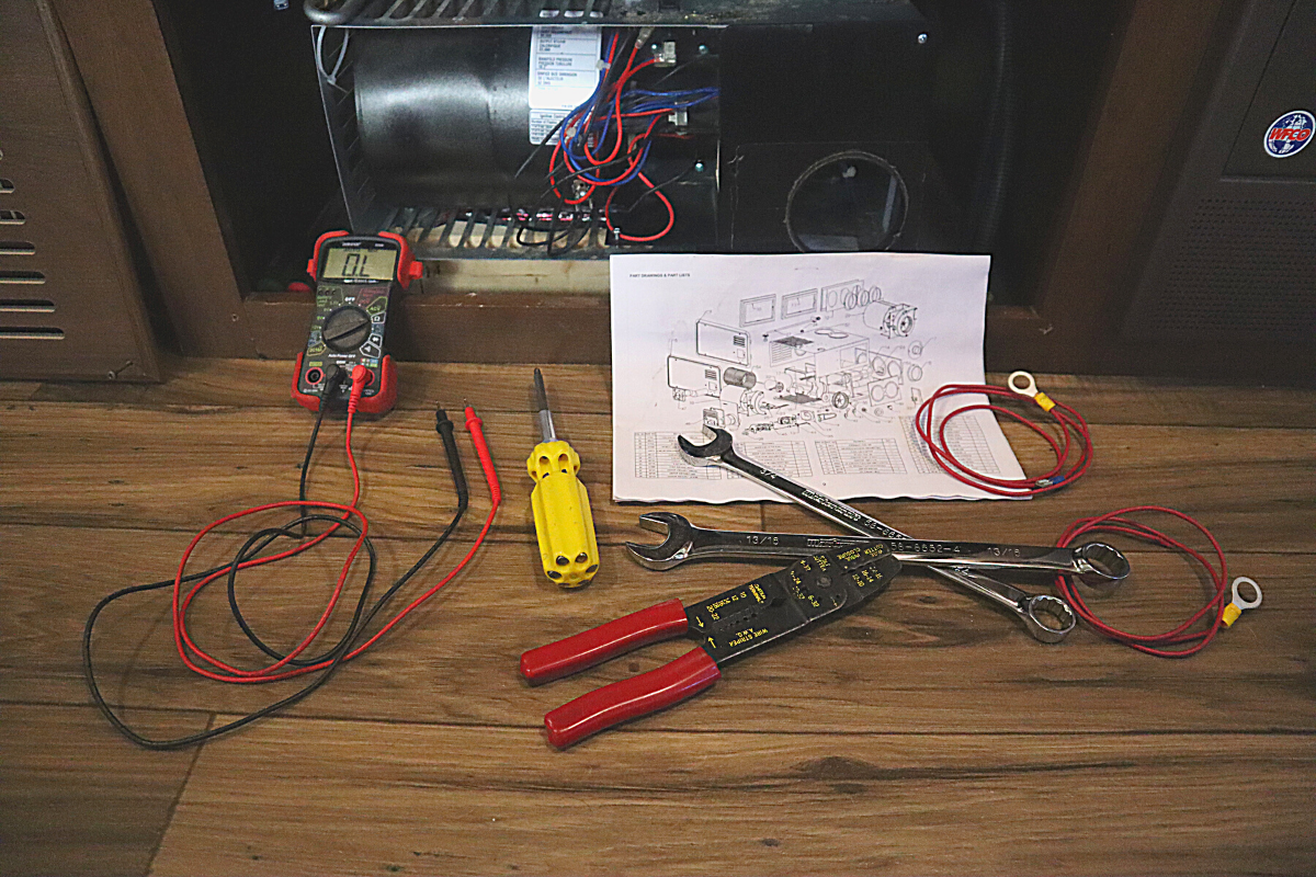
Here are the tools you might need:
- Multimeter
- Screwdriver
- Wrenches
- Test leads
- 12-volt power source
- Furnace manual
Safety disclaimer: It’s important to note your RV furnace operates using propane and electricity, two potentially dangerous sources. Therefore, if you are not confident in working with either, allow a professional technician to take care of the repairs.
How electricity works in your RV
Electricity is the heartbeat of your RV. Here is a simplified breakdown of how it works:
- Current is the flow of energy pushed through a circuit. In the case of most RVs, it is 30 or 50-amps.
- Voltage is the pressure that pushes the current from the power source through the electrical circuit. In the case of most RVs, it is 120-volts.
- Resistance is the force against the current flow; measured in ohms.
- DC or direct current is the 12-volt power from your RV battery or batteries. It provides power for the start-up of your furnace, water heater, and fridge. DC powered items include your water pump, carbon monoxide detector, and most lights.
- AC or alternating current is the 120-volt power you get from your RV’s electrical hook-up. It provides power for the electrical outlets you plug daily use items into like kitchen appliances, laptops, phone chargers, and your TV.
3 major components make up an electrical circuit:
- A “load” is something that needs electricity to operate such as a light or microwave.
- A “source” provides that electricity such as a battery or a generator.
- A “conductive path” transfers the electricity from the source to the load such as a wire or circuit board.
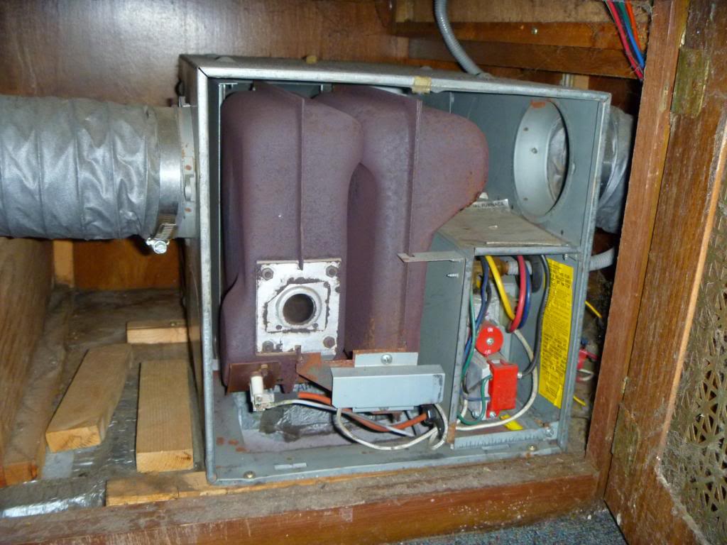
Testing the RV furnace components
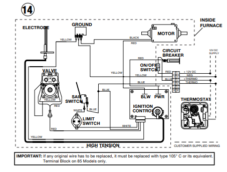
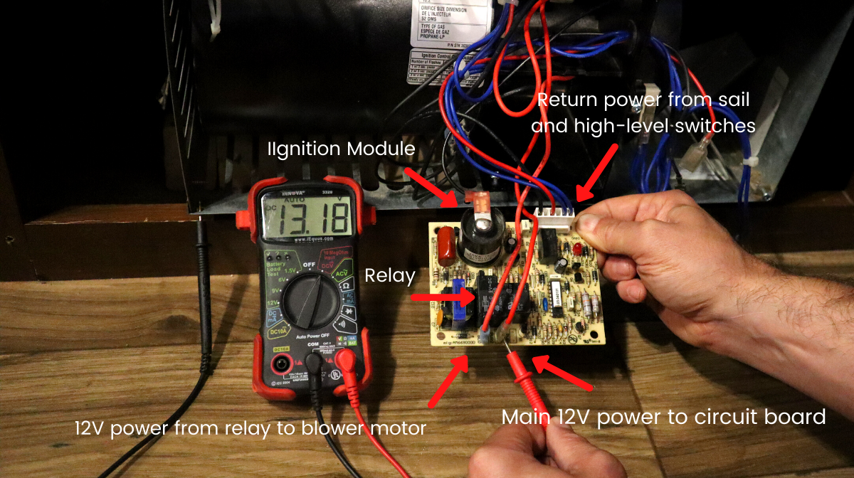
Circuit board and relay
The purpose of these tests are to ensure that power is traveling to the circuit board and to ensure power is traveling through the circuit board to the other RV furnace components and back.
To check that power is coming to the circuit board, set your multimeter to DC volts. Attach one lead to a ground and the other to the connection where the main power connects to the circuit board. The reading should be at least 12V at all times.
To check the relay on the circuit board, attach one lead to the connection after the relay that leads to the blower motor and the other to a ground. With the thermostat on, this should have the same reading as the above test. This will determine if the power is making it past the relay to the blower motor.
To confirm the power is making it through the circuit and back to the circuit board, check the connections on the circuit board where the power returns from the sail and high-level switches. Once again, with the thermostat on, the reading on the multimeter should be above at least 12V.
Also visually inspect the circuit board, looking for any burnt or discolored areas or physical damage.
Blower motor
To test the blower motor on its own, you will need a 12V power supply like an RV or car battery. Next, place the test leads to join the positive and negative wires of the blower motor to the positive and negative terminals of the battery. The fan should start immediately.

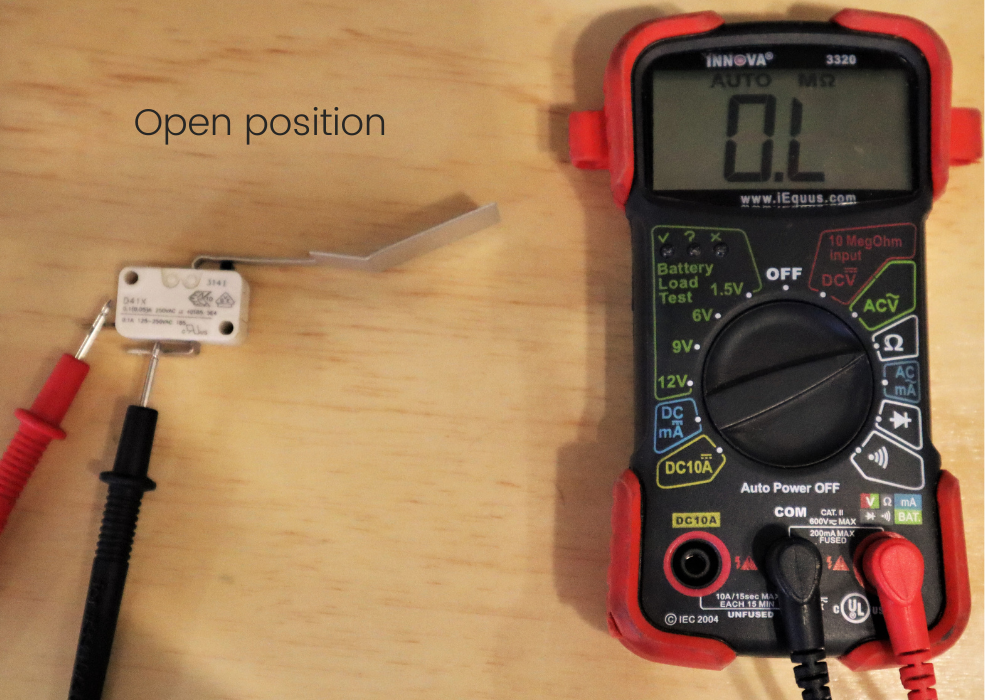
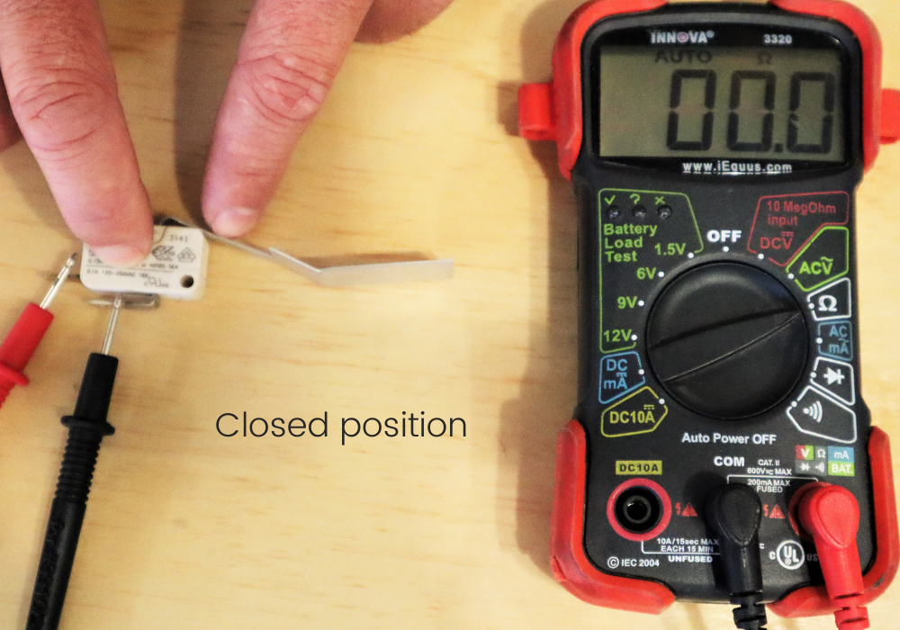
Sail switch
Before engaging, the sail switch is an opening in the electrical circuit. To complete the circuit, the sail switch must close allowing the current to pass through it.
With the sail switch removed, test with a multimeter set to ohms. Attach the red and black leads, one to each of the two connections on the sail switch. There will be an “OL” or “open line” reading on the meter since the sail switch is in the open position. By hand, close the sail switch. With the circuit closed, there should now be a reading of approximately 0.0 – 0.2 if the switch is good.
High-level switch
The high-level switch, when not engaged, is in a closed position. If the temperature in the combustion chamber rises above a safe level, it opens the high-level switch breaking the closed-circuit and shutting down the furnace.
It’s easiest to test with the switch removed. Attach the red and black leads of the multimeter – again set to ohms – to the two terminals on the switch. If the switch is good, there should be a reading similar to that of a good sail switch. If it reads “OL” or “open line” then the switch is bad.
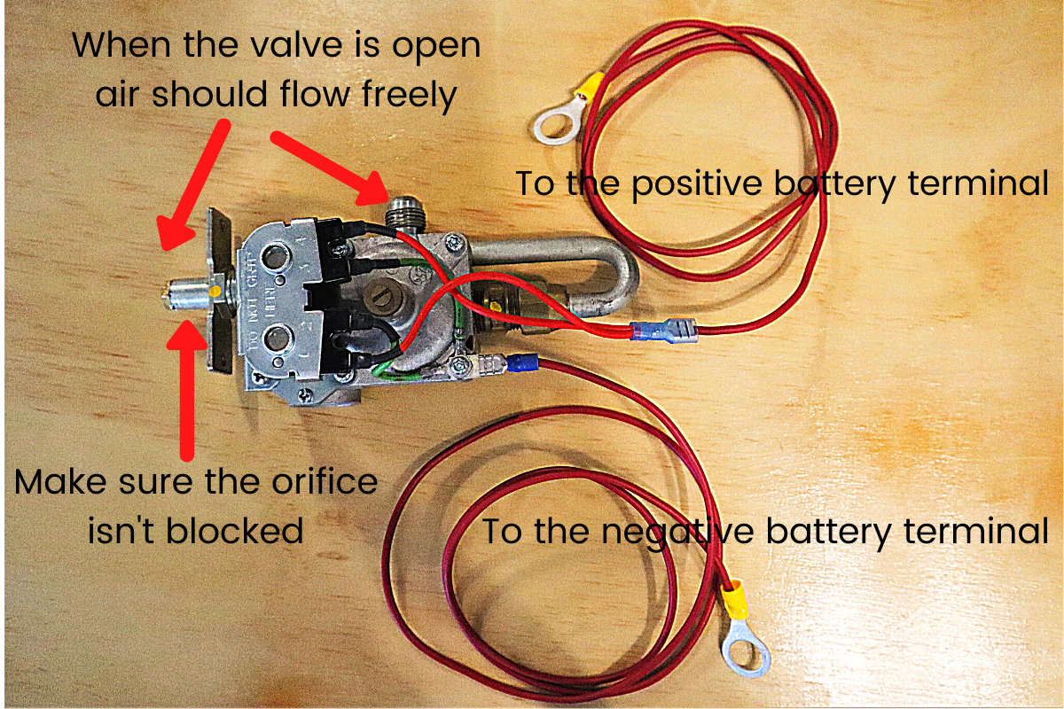
Gas valve
The gas valve will require a 12V power source to test if it’s opening. The easiest source is an RV or car battery. You will need two test leads to connect the positive and negative connections on the valve to the positive and negative terminals on the battery. When connected, the valve should open and you should be able to blow air through the connections for the gas line. If not, it isn’t opening.
Ignitor
With the ignitor removed from the combustion chamber but still connected to the furnace (make sure your gas is disconnected), you should see a spark jumping between the ignitor tips when the furnace is trying to start.
Visually inspect the ceramic insulation for cracks. Check that the manufacture specified gap between ignitor tips is okay. Ensure that the gas chamber is in good condition with no large holes that would allow gas to escape before being ignited.
If there is no spark and you don’t hear the fast ticking of the ignitor, then the ignition module on the circuit board is likely bad.
Flame sensor
The test for the flame sensor is more complicated. It will need to be in contact with a flame. Therefore, leaving it installed in the furnace is the easiest way to test it.
You will also need a multimeter that will read in DC microamps and a specific capacitor to perform this test. The leads of your multimeter will be connected inline between the flame sensor and the capacitor as seen in the video below.
Note: The flame sensor and ignitor are generally part of the same assembly if replacing.
Many of the components in your furnace are the same as in your hot water heater, refrigerator, and AC systems. Therefore, many of the same tests would apply and can help you in troubleshooting and repairing these systems.
Share your experiences with RV furnace troubles and repair in the comments below, on our Facebook page, or share them with the RV community on iRV2 Forums.